How to Read Construction Plans
The complete Australian guide to interpreting construction drawings. Master site plans, floor plans, elevations, sections, and specifications — an essential skill for every builder, site supervisor, and construction professional.
TL;DR
Construction plans are the language of building — mastering site plans, floor plans, elevations, sections, and structural drawings is essential for every builder and supervisor. All Australian dimensions are in millimetres, and you must always cross-reference drawings with specifications. Check title blocks for current revisions, learn standard symbols, and never assume when plans conflict.
Why Plan Reading Matters
Construction plans are the language of building. They communicate the architect's and engineer's intent to everyone on site — from the excavator operator to the finishing carpenter. Knowing how to read them accurately is one of the most valuable skills you can develop.
Whether you're a new builder, an aspiring site supervisor, or a tradesperson wanting to understand the bigger picture, this guide will walk you through everything you need to know about interpreting Australian construction drawings.
Poor Plan Reading Leads To
- Costly rework and project delays
- Incorrect material ordering
- Building defects and non-compliance
- Disputes with clients and trades
Good Plan Reading Enables
- Accurate quoting and estimating
- Efficient construction sequencing
- NCC compliance confidence
- Clear trade communication
Key Principle
Verify You Have Current Documents
Before diving into any plans, always confirm you have the latest versions of all drawings and specifications. Using outdated plans is one of the most common — and costly — mistakes on building sites.
The Title Block
Critical Information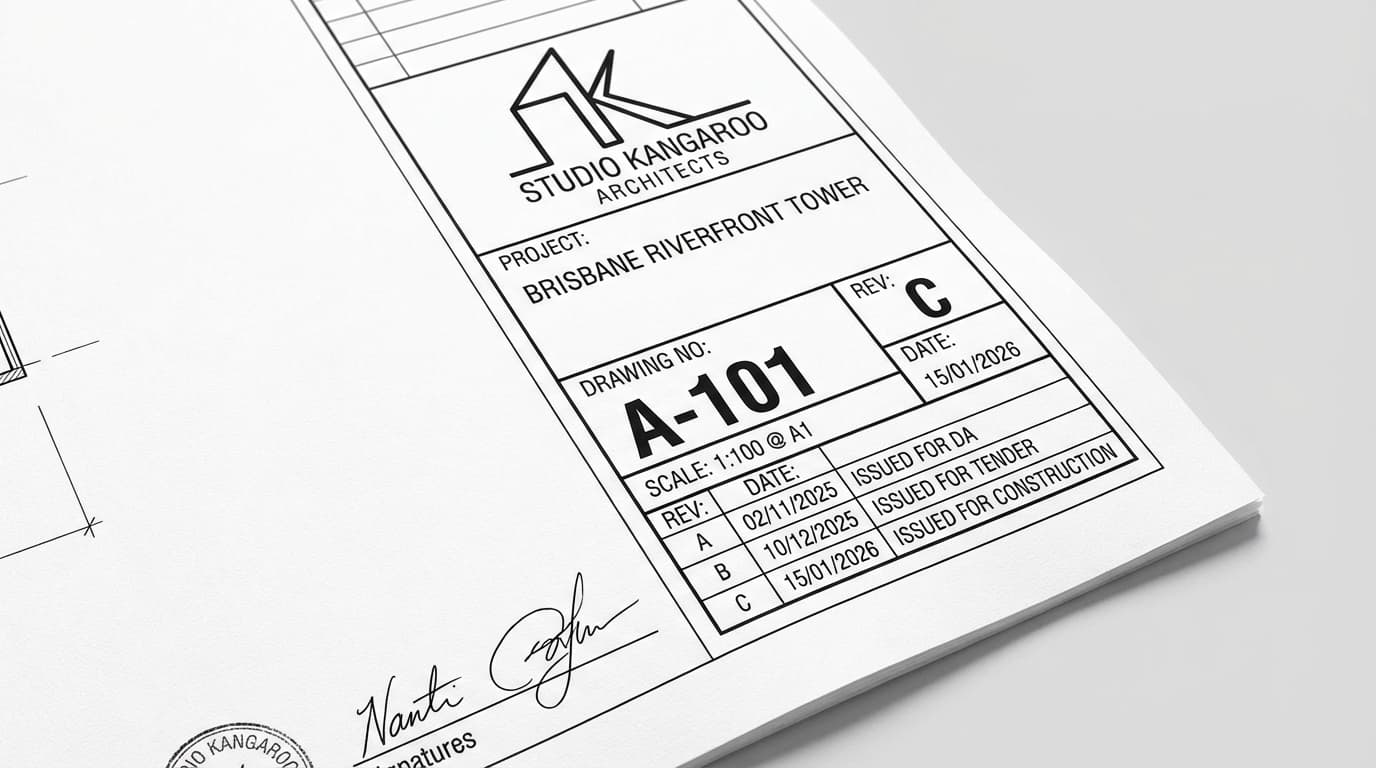
What to Check
Every drawing has a title block, typically in the bottom-right corner. It contains critical information:
- Drawing Number — Unique identifier (e.g., A-101)
- Revision — Current version (A, B, C or 1, 2, 3)
- Date — When this revision was issued
- Scale — How to measure the drawing
- Project Name — Confirms you have the right project
- Prepared By — The firm responsible
Always cross-check against the drawing register or transmittal to ensure you have all current sheets.
Revision Clouds
Plans vs Specifications
Specifications: Written document — materials, quality standards, installation methods
These documents work together. If the plan shows a window, the specification tells you the brand, model, glazing type, and installation requirements. If you find a discrepancy, raise it immediately — don't assume one is correct.
Types of Construction Drawings
A typical residential construction project includes multiple drawing types, each serving a specific purpose. Understanding what each type shows helps you find information quickly.
| Drawing Type | What It Shows | Common Scales | Prefix |
|---|---|---|---|
| Site Plan | Building position on the lot, boundaries, setbacks, levels, services | 1:200, 1:500 | A |
| Floor Plans | Room layouts, walls, doors, windows, fixtures | 1:100, 1:50 | A |
| Elevations | External views of each face of the building | 1:100, 1:50 | A |
| Sections | Cut-through views showing internal construction | 1:100, 1:50 | A |
| Details | Close-up views of specific construction elements | 1:20, 1:10, 1:5 | A |
| Structural Plans | Footings, slabs, beams, columns, bracing | 1:100, 1:50 | S |
| Electrical Plans | Power points, lighting, switches, smoke detectors | 1:100 | E |
| Plumbing Plans | Pipe runs, fixtures, drainage | 1:100 | P |
Drawing Numbering
Reading the Site Plan
The site plan is your starting point. It shows the "big picture" — how the building sits on the land. Always begin here to understand the overall context.
Key Site Plan Elements
Scale: 1:200 Typical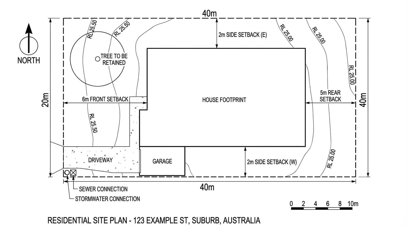
What to Identify
- Property Boundaries — Legal extent of the land
- Building Footprint — Where the building sits
- Setbacks — Distances to front, side, rear boundaries
- North Arrow — Building orientation (critical for solar)
- Contour Lines — Existing ground levels (RLs)
- Datum/Benchmark — Reference point for all heights
- FFL — Finished Floor Level of the building
- Services — Water, sewer, stormwater connections
- Easements — Areas you can't build on
- Existing Features — Trees, structures to retain/remove
Reduced Levels (RL)
Service Connections
Reading Floor Plans
The floor plan is the most frequently referenced drawing on site. It's a horizontal "slice" through the building at about 1.2 metres above the floor, looking down.
Understanding the Floor Plan View
Horizontal Section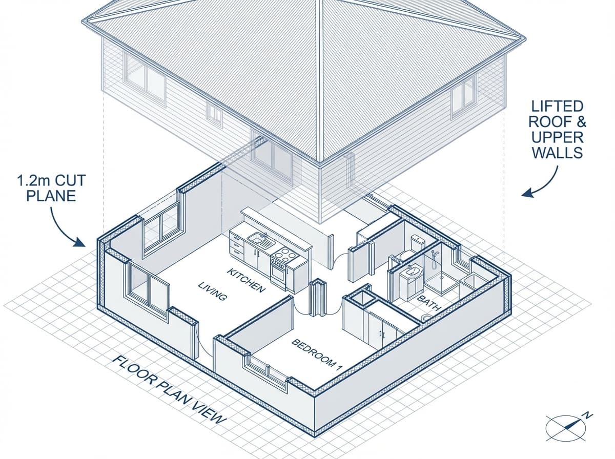
The Concept
Imagine slicing through the building at about 1.2 metres above the floor and removing everything above. What you see looking down is the floor plan.
This is why you see:
- Windows (the cut goes through them)
- Doors with swing arcs
- Kitchen and bathroom fixtures
- Walls at their full thickness
But you don't see high shelves, ceiling details, or roof structure.
Wall Types and Line Weights
| Line Type | Typically Indicates | Visual |
|---|---|---|
| Thick solid lines | External walls | ━━━━━━━━ |
| Medium solid lines | Internal load-bearing walls | ──────── |
| Thin solid lines | Partition walls (non-structural) | ──────── |
| Hatched/filled | Brick, concrete, or masonry | ▓▓▓▓▓▓▓▓ |
Always Confirm Load-Bearing Walls
Reading Dimensions
All Australian Dimensions Are in Millimetres
Dimension strings typically run in layers: overall building dimensions on the outside, then major elements, then detail dimensions on the inside. Always verify by adding up smaller dimensions to check they equal the overall.
Doors and Windows
Standard Symbols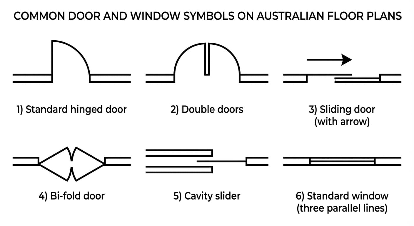
Door Symbols
- Hinged door — Arc shows swing direction
- Sliding door — Arrow shows slide direction
- Bi-fold door — Zigzag lines
- Cavity slider — Slides into the wall
Window Symbols
- Breaks in walls with parallel lines for glass
- Tags (W1, W2) reference the window schedule
Door and window schedules list size, type, material, and hardware for each tagged opening.
Reading Elevations
Elevations are flat, straight-on views of each external face of the building. They show what the building looks like from the outside and provide critical information about heights and materials.
Four Elevations
North • South • East • West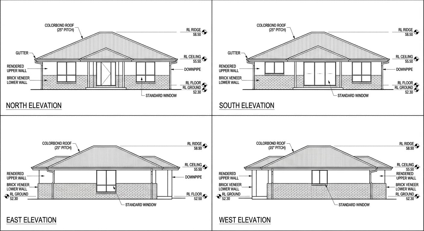
Key Information on Elevations
- Heights & Levels — GL, FFL, FCL, Ridge as RLs
- External Materials — Brick, render, cladding, roofing
- Roof Information — Material, pitch (degrees), gutters
- Window/Door Tags — Same tags as floor plan
- Downpipes — Location for stormwater
Level Abbreviations
- GL — Ground Level
- FFL — Finished Floor Level
- FCL — Finished Ceiling Level
Reading Sections
Section drawings are cut-through views showing the internal construction of the building. They're essential for understanding how the building is actually assembled — the layered construction of floors, walls, and roofs.
How Sections Work
Cut-Through View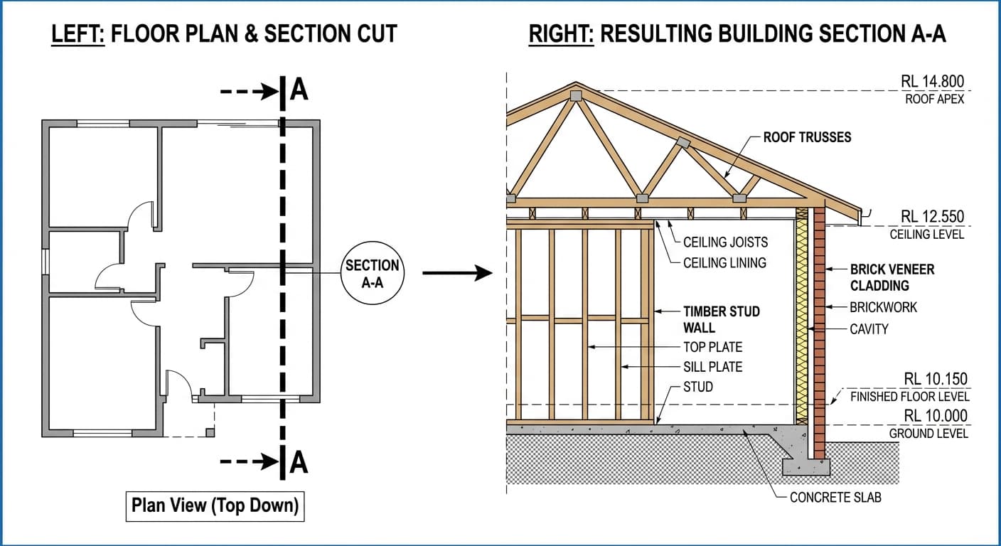
Understanding the View
On a floor plan, you'll see a section line — a line with arrows at each end showing where the imaginary cut is made and which direction you're looking.
What Sections Reveal
- Floor construction — Slab thickness, reinforcement
- Wall build-up — Studs, insulation, cladding, lining
- Roof structure — Trusses, insulation, battens, roofing
- Heights — Floor-to-ceiling dimensions
- Structural elements — Beams, lintels, connections
Detailed Wall Section
Typical Australian Construction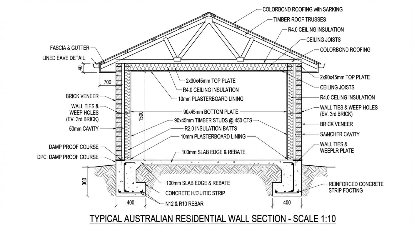
Reading the Layers
A section shows you every layer from outside to inside:
- External: Brick veneer or cladding
- Cavity: Air gap with wall ties
- Frame: Timber studs (e.g., 90x45 @ 450 CTS)
- Insulation: Batts between studs
- Internal: Plasterboard lining
Look For
- Stud size and spacing (90x45 @ 450 CTS)
- Insulation R-values
- Vapour barriers and sarking
- Connection details
Reading Structural Drawings
Structural drawings focus on the load-bearing elements that keep the building standing. They're prepared by a structural engineer and include footings, slabs, beams, and bracing.
Footing Plan
Shows location and type of all footings (strip, pad, pier). References a footing schedule listing width, depth, and reinforcement for each footing type (F1, F2, etc.).
Slab Plan
Shows slab thickness, reinforcement mesh type, edge beam details, step-downs, and penetrations for plumbing. Critical for concrete pours.
Beam Schedule
Lists all beams and lintels with reference mark, size and type (timber, LVL, steel), span, and support requirements.
Bracing Plan
Shows wind bracing locations, types (ply, metal strap), and units achieved vs. required. Ensures the building can resist wind forces.
Footing Schedule Example
F1: 450W x 300D, 4-N12 bars, N10 ties @ 300 CTSF2: 600W x 450D, 6-N12 bars, N10 ties @ 250 CTS
This tells you: F1 footing is 450mm wide, 300mm deep, with 4 x N12 reinforcement bars and N10 ties at 300mm centres.
Symbols and Abbreviations
Construction drawings use standardised symbols and abbreviations. Always check the legend (usually on the first sheet) for project-specific meanings.
Common Abbreviations
RLReduced LevelFFLFinished Floor LevelFCLFinished Ceiling LevelGLGround LevelNGLNatural Ground LevelTOCTop of ConcreteBOCBottom of ConcreteDPCDamp Proof CourseDPMDamp Proof MembraneNTSNot to ScaleTYPTypicalSIMSimilarCTSCentres (spacing)CLGCeilingCJControl JointEJExpansion JointEQEqualMAXMaximumMINMinimumNOMNominalUNOUnless Noted OtherwiseHWUHot Water UnitWMWashing MachineDPDownpipeCommon Symbols
Always Check the Legend
Using Specifications
The specification is the written companion to the drawings. It provides details that can't be shown graphically — exact materials, quality standards, and installation methods.
Materials
Exact product, brand, model, and grade. For example: "Boral Blue Circle GP Cement" or "James Hardie Scyon Linea 180mm".
Quality Standards
Standards to meet, such as "concrete to AS 3600" or "waterproofing to AS 3740". These are legally binding.
Installation Methods
How to install, fix, or apply. For example: tile adhesive type, fixing centres, curing times.
Finishes
Final appearance — paint colours, tile grout colour, surface textures, polish levels.
PC and PS Items
Prime Cost (PC) Items
• Bathroom tapware — PC $800
• Kitchen appliances — PC $3,500
• Light fittings — PC $2,000
If selection costs more than allowance, owner pays the difference.
Provisional Sums (PS)
• Rock excavation — PS $5,000
• Landscaping — PS $8,000
• Electrical rough-in — PS $4,500
These represent unknowns that could affect final cost.
Practical Tips for Plan Reading
These tips will help you read plans more effectively and avoid common mistakes.
Start with the Big Picture
Always start with the site plan, then floor plan, elevations, sections, and finally details. Work from general to specific.
Cross-Reference Constantly
A dimension on the floor plan should match the section. A material on the elevation should match the spec. Cross-referencing catches errors.
Use the Correct Scale
Check the stated scale. Remember: printed copies may be reduced. An A1 drawing at A3 is at half scale.
Read All Notes
Don't skip the small print. General notes and specific annotations contain critical information not shown graphically.
Query Discrepancies
If something doesn't make sense or two drawings conflict, ask. Never assume or guess. A quick clarification prevents expensive mistakes.
Visualise in 3D
Build a 3D mental model as you read. Trace a wall from plan to section. Follow a beam to where it appears in elevation. Everything should connect.
Free Tools for Builders and Site Supervisors
Built by Prepare Training (RTO 45384). Use them on the job today, no account needed.
- Free SWMS generator
Draft a site-specific Safe Work Method Statement for high risk construction work in minutes. No sign-up.
Open the tool → - Free building materials calculator
Work out concrete, brick, timber and plasterboard quantities with waste allowances built in.
Open the tool → - Free construction cost calculator
Instant per-square-metre build estimates for Sydney, Melbourne, Brisbane, Perth and Adelaide.
Open the tool →
Already reading plans on site every day?
Frequently Asked Questions
Plan reading is a core competency in the Certificate IV in Building and Construction (CPC40120) and the Diploma of Building and Construction (CPC50220). Both qualifications are available 100% online with Prepare Training.
Ready to Formalise Your Building Knowledge?
Plan reading is a core competency in the Certificate IV and Diploma of Building and Construction. Our 100% online courses give you the qualifications you need for your builder's licence.